Seven Long Questions on Power Transmission
Question.1. Define belts. What are its different types? Explain.
Answer.
The flexible wrapping connectors (belt and ropes) are used to transmit power from one shaft to another. When the wrapping connector takes the form of a band, whose thickness is small in comparison to width, it is called a belt.
Types of Belts : These days, there are many types of belts in use. Some important types of belts are as follows:
(a) (b) (c) (d)
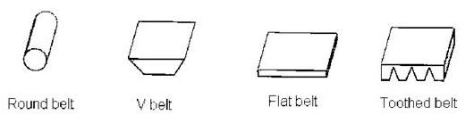
Fig. Types of Belts
- Round Circular or Rope Belt: The belt having circular cross-section is known as circular belt or rope as shown in figure.(a). In factories, it is used for power transmission, when the distance between the pulleys is more than 8 metres.
- V-Belt : The belt having trapezoidal cross section is known as V-Belt as shown in fig. (b). It is mostly used in factories and workshops for transmitting large amount of power, when the two pulleys are close to each other. To take the advantage of the wedge action, the groove on the rim of the pulley is made deeper. The belt does not touch the bottom of the groove. It needs little adjustment. Due to wedging action, it can transmit more power as compared to flat belts. For transmitting more power between the two pulleys, multiple V-belts can be used.
- Flat Belt : A belt having rectangular cross-section is known as flat belt as shown in fig. (c). It is mostly used in factories for moderate power transmission from one pulley to another at a distance not more than 8 metres. In this case, the rim of the pulley is slightly crowned as it helps to keep the belt running centrally on the rim of the pulley.
- Toothed Belt : These are the non slipping mechanical drive belts. These are made as flexible belts on the inner surface of which teeth are moulded as shown in figure (d). These belts move over the matching toothed pulley or sprockets
Question. 2. Explain different types of pulleys used for flat belt.
Answer.
The various types of pulleys for flat belts are as follows:
- Cast iron pulleys,
- Steel pulleys,
- Wooden pulleys,
- Fast and loose pulleys.
- Cast Iron Pulleys : These pulleys are made of cast iron. The rim is held in place with the help of arms from the hub. The arm may be straight or curved. However, a cast iron pulley with straight arms is shown in fig. The cross section of the arms is usually elliptical.
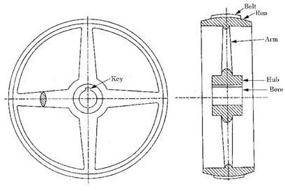
Fig. Cast Iron Pulley
- Steel Pulleys : These pulleys are made from pressed steel sheets and possess greater strength and durability. These pulleys are designed to run at high speeds and are lighter in weight (about 40% to 60% less) as compared to cast iron pulleys of the same capacity.
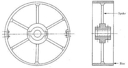
Fig. Mild Steel Pulley
- Wooden Pulleys : These pulleys are lighter in weight (about 2/3rd of the weight of the cast iron pulleys of the similar size) and possess higher coefficient of friction as compared to cast iron or steel pulley. These pulleys are generally made from selected maple which is laid in segments and glued together under heavy pressure. The protective coating of shellac or varnish is applied on these pulleys to keep them from absorbing moisture so that no warpage occurs. The hubs of these pulleys are of cast iron.
- Fast and Loose Pulleys : In this arrangement, one pulley called fast pulley is keyed to the shaft, while the other pulley called loose pulley rotates freely on the shaft. In this, the driven shaft can be started or stopped without interfering with the running of driving shaft. To stop the driven shaft, the belt is shifted to the loose pulley. Fig. shows the sectional view of a set of fast and loose pulleys. The fast pulley is keyed to the shaft with the help of the gib head key. For the free running of the loose pulley, a brass or gun metal bush is provided, which has driving fit in the hub and the running fit on the shaft. To prevent the axial movement of the loose pulley, a collar is secured to the shaft by a set of screw.
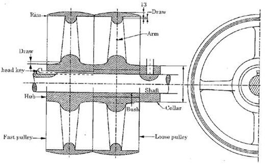
Fig. Fast and Loose Pulleys
Question.3. Define slip. Derive an expression for the total slip between belt and pulley.
Answer.
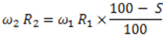
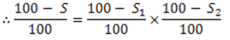
If the difference in tension between tight and slack sides of the belt is too large to be resisted by friction between the belt and the pulley, the whole of the portion of the belt which is in contact with the pulley begins to slide. This results in relative motion between the belt and the pulley and is called slip. It is generally expressed in percentage. The effect of the slip is to reduce the velocity ratio of the drive.


![]()


Question. 4. Derive an expression for ratio of tensions in flat belt.
Answer.
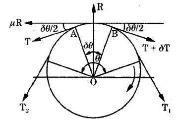
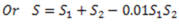
Fig. Ratio of Tensions for Flat Belt
Let us consider a driven pulley rotating in clockwise direction as shown in fig.


For short strip AB to be in equilibrium,

As  is small, so
  ,
,
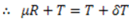


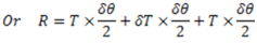
Since, the product of two small quantities can be neglected,
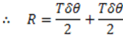
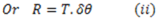
Substituting the value of R from equation (ii) in equation(i)


Integrating both sides within proper limits,


Question. 5. Derive an expression for centrifugal tension in case of belts drive.
Answer.
When the belt continuously moves over the pulley, the centrifugal force due to its own weight tends to fit it from the pulley. This centrifugal force produces equal tensions on tight and slack side of the belt known as centrifugal tension.
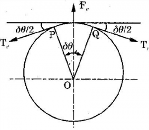
Fig. Centrifugal Tension
Let us consider a short strip PQ of the belt subtending an angle  at the centre of pulley O as shown in fig.


![]()


Also from fig.
As  is small,
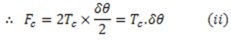
From equation (i) and (ii), we get

Which shows that centrifugal tension is independent of the tensions on tight and slack side of the belt and depends upon the velocity of the belt over the pulley.


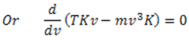
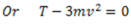
Question.6. Derive an expression for condition for transmission of maximum power by belt.
Answer.
We know that power transmitted by a belt,
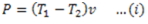


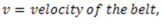
We also know that the ratio of tensions is given by


Putting the value of  in equation (i), we get


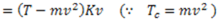
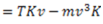
For transmission of maximum power,


Question.7. Explain gear nomenclature with the help of neat sketch.
Answer.
The terminology of gear teeth is illustrated in figure given below:
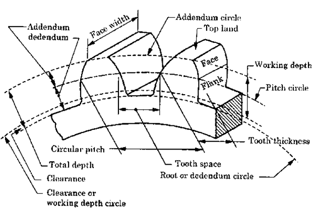
Fig. Gear Nomenclature
- Pinion : A pinion is the smaller of two mating gears. The larger is often called gear or the wheel.
- Rack : It is a gear with infinite diameter as shown in figure (b).
- Pitch Cylinder : Pitch cylinders of a pair of gears in mesh are the imaginary friction cylinders which roll together without slip to give the same velocity ratio as the pair of mating gears.
- Pitch Circle : It is the theoretical cylinder on which all the calculations are usually based. The pitch circles of a pair of mating gears touch each other. The diameter of the pitch circle is called pitch circle diameter.
- Pitch Point: It is the point of contact of two pitch circles.
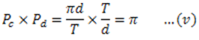
- Circular Pitch (
 ): It is the distance measured on the pitch circle from a point on one tooth to a corresponding point on the next tooth. Mathematically,

The angle subtended by the circular pitch at the centre of the pitch circle is called pitch angle.
- Module : It is the ratio of the pitch circle diameter to the number of teeth. Mathematically,
- Diametral Pitch(
 ): It is the number of teeth on the gear per unit of the pitch circle diameter. Mathematically,
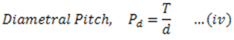
From equation (i) and (iv), we get
- Addendum Circle : It is the circle passing through the top of the teeth and is concentric with the circle. It is also called tip circle.
- Addendum : It is the radial distance from the pitch circle to the top of the tooth. Its standard value is one module.
- Dedendum Circle : It is the circle drawn through the bottom of the teeth and us concentric with pitch circle. It is also called root circle.
- Dedendum : It is the radial distance from the pitch circle to the tooth. Its standard value is 1.157m.
- Clearance : It is the difference between dedendum and addendum.
- Backlash : It is the amount by which the width of a tooth space exceeds the thickness of the engaging tooth on the pitch circles.

- Top Land : It is the surface of the top of the tooth.
- Face Width : It is the length of the tooth parallel to the parallel to the gear axis.
- Face : It is the tooth surface between the pitch circle and the and the top land.
- Flank : It is the tooth surface between the pitch circle and the bottom land.
- Bottom Land : It is the surface of the bottom of the tooth between adjacent fillets.
- Fillets : It is the curved portion of the tooth flank at the root circle.
- Total Depth : It is the radial distance between the addendum circle and the dedendum circle of a gear. It is equal to the sum of addendum and dedendum.

- Working Depth : It is the maximum depth in which a tooth penetrates into the tooth space of the mating gear.

- Line of Centres : It is the line connecting the centres of a pair of mating gears.
- Pressure Angle or Angle of Obliquity : It is the inclination of the line of action between a pair of mating teeth to the line drawn tangent to the pitch circle at the pitch point.
In other words, we can say that it is the angle between the common normal to the gears at the point of contact and the common tangent at the pitch point. The standard pressure angles are  .
.