Eleven Questions on Simple Mechanism
Question.1. Differentiate between machine and structure.
Answer.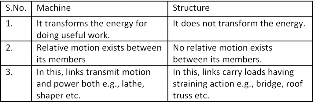
Question.2. Draw a neat sketch of four bar chain.
Answer.
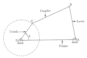
Fig. Four Bar Chain
Question.3. Draw a neat sketch of slider crank.
Answer.
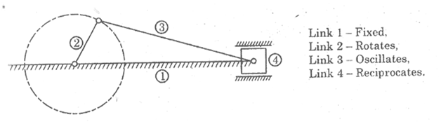
Fig. Slider Crank Chain
Question.4. Draw a neat sketch of double slider crank chain.
Answer.
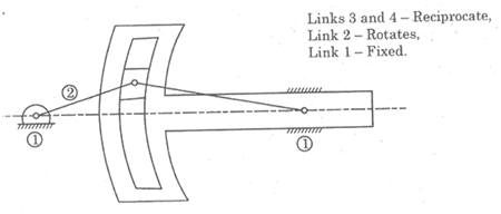
Fig. Double Slider Crank Chain
Question.5. Define link. What are its different types? Explain.
Answer.
Each part of machine which moves relative to the other is called kinematic link or element.
A link or an element may consist of a number of parts connected in such a way that they form one unit and have no relative motion with each other. e. g. piston, piston-rod and cross-head of a steam engine constitute one unit and will be taken as one link or element. Similarly, the crank pin, crank webs, crank shaft, flywheel etc. constitute another unit and will be taken as one link. On the other hand, cross head, connecting rod, crank and frame of steam engine are different links.
The link may be rigid such as crank, connecting rod etc. of a steam engine or may be flexible such as belts or may be fluid such as fluid used in hydraulic presses, hydraulic brakes and hydraulic jacks.
Types of Links: To transmit the motion, the driver and the follower may be connected with the help of following three types of links:
(i) Rigid link,
(ii) Flexible link,
(iii) Fluid link.
(i) Rigid link : A rigid link is one which does not undergo any deformation while transmitting motion. In actual practice, no link is perfectly rigid, but as deformation of connecting rod, crank etc. is negligible, so these can be considered as rigid.
(ii) Flexible link : A flexible link is that which, while transmitting motion, is partly deformed in such a manner that transmission of motion is not affected. Such a link transmits motion in one direction only (push or pull). e.g., belts, ropes spring, chains etc.
(iii) Fluid link : It is formed by having fluid in receptacle and motion is transmitted through the fluid by pressure or compression. e.g., hydraulic jack, hydraulic brakes etc.
Question.6. Explain different types of constrained motion.
Answer.
The motion which takes place in a definite direction is called constrained motion.
The three types of constrained motion are as follows:
1. Completely Constrained Motion: When the motion between a pair is in a definite direction irrespective of the direction of the applied force, such motion is known as completely constrained motion. e.g., the motion of the piston in a cylinder of an internal combustion engine takes place in a definite direction and is therefore a completely constrained motion. Other examples are: a square bar in a square hole fig. (a), a shaft with collars at each end rotating in a circular hole fig (b).
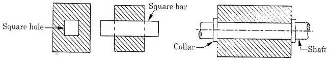
Fig. (a) Square Ball in a Square Hole (b) Shaft with a collar in a Circular Hole
2. In completely Constrained Motion: When the motion between the pair takes place in more than one direction, such motion is known as incompletely constrained motion e.g., a circular bar in a circular hole fig. as the bar can reciprocate or rotate, Both the motion have no relationship between them.
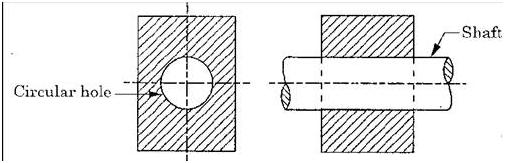
Fig. Shaft in a Circular Hole
3. Partially or Successfully Constrained Motion.: When the constrained motion between pair is not completed by itself, but by some other means, such motion is known as partially or successfully constrained motion e.g., the shaft in the foot step bearing shown in fig. may rotate or may move upwards and is therefore an example of incompletely constrained motion. Now if we apply the compressive load on the shaft to prevent its upward movement, then the motion is said to be successfully constrained motion. Other examples are : Engine valves, piston reciprocating inside an engine cylinder.
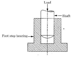
Fig. Shaft in a Foot step Bearing
Question.7. Give the complete classification of kinematic pairs and explain.
Answer.
Kinematic pairs may classified according to
(A) Type of contact between the elements.
(B) Type of closure between the elements.
(C) Type of relative motion between the elements.
(A) Type of Contact Between the Elements
(i) Lower pair : The kinematic pair which has surface contact between its links while transmitting motion is known as lower pair. e. g., shaft revolving in bearing, piston reciprocating in the cylinder of an I C engine.
(ii) Higher pair : The kinematic pair which has point or line contact between its links while transmitting motion is known as higher pair e g .belts ropes and chain drives, cams ball and roller bearings.
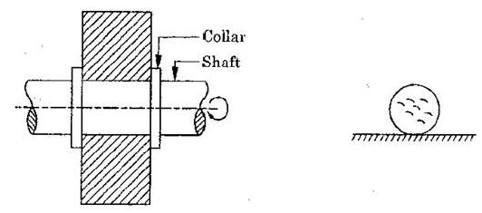
(Shaft with collar in Circular Hole) (Ball Rolling on the Ground)
Lower pair Higher pair
(B) Type of Closure between the Elements
(i) Open Pair : When two links of a kinematic pair are not held together mechanically, but remain in contact with each other under the action of forces, then such a pair is called an open pair. e.g. cam and follower shown in fig.
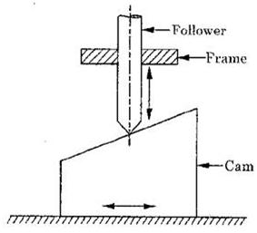
Fig. Open Pair
(ii) Closed Pair : When two links of a kinematic pair are held together mechanically in a such a way that only required type of relative motion occurs, then such a pair is called closed pair. e.g. screw pair, spherical pair etc.
(C) Type of Relative Motion between the Elements
(i) Sliding Pair : When two links of a kinematic pair are connected in such a way that one link slides relative to the another, the pair is called a sliding pair. As a sliding pair has surface contact between its links, so it is kind of lower pair. e.g. square bar in a square hole as shown in Fig.(a) piston reciprocating in the cylinder of an i.c. engine.
(ii) Turning Pair : When two links of a kinematic pair are connected in such a way that one link can only turn or revolve about fixed axis of another link, the pair is called a turning pair. e.g. a shaft revolving in a bearing, circular shaft in a circular hole as shown in fig. (b), lathe spindle supported in a head stock etc.
(iii) Rolling Pair : When two links of a kinematic pair are connected in such a way that one link rolls on another link, the pair is called a rolling pair. e.g. belt and pulley as shown in fig.
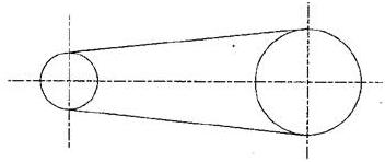
Fig. Belt and Pulley
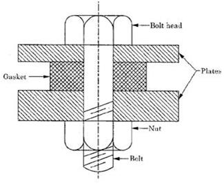
(iv) Screw Pair : When two links of a kinematic pair are connected in such a way that one turns about another link by mans of threads, the pair is called a screw pair. e.g. lead screw of a lathe, assembly of a nut and bolt as shown in fig.
(v) Spherical Pair : When two links of a kinematic pair are connected in such a way that one link in the form of sphere turns or swivel about another fixed link, the pair is called spherical pair. e.g. ball and socket joint as shown in fig. pen stand etc.
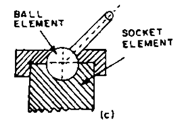
Fig. Ball and Socket Joint
Question.8. Explain the application of four bar chain with the help of neat sketches.
Answer.
The followings are the applications of four bar chain:
(i) Beam Engine (Crank and Lever Mechanism) : It consists of four links as shown in fig. this mechanism is used for converting rotary motion into reciprocating motion. When the link 2 (crank) rotates about A, link 4 (Lever) oscillates about a fixed centre D. The end of link 4 is connected to the piston rod which causes the piston to reciprocate in the cylinder.
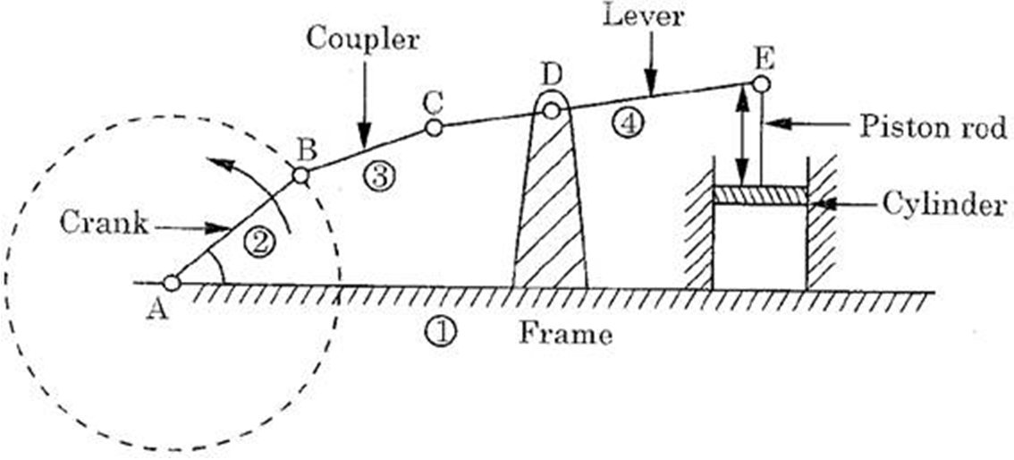
Figure. Beam Engine
(ii) Coupled Wheel of Locomotive (Double Crank Mechanism)
This mechanism is used to transmit rotary motion of one wheel to another wheel.
In this mechanism, the link 2 and 4 shown in fig. are of equal lengths and act as cranks. These cranks are further connected to two driving wheels. The link 1 is kept fixed to maintain constant distance between the wheels and link 3 acts as connecting rod.
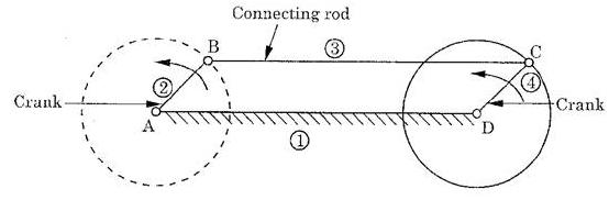
Fig. Coupled Wheels of Locomotives
(iii) Engine Indicator (Double Lever Mechanism) :
This mechanism was used by Watt in steam engine to guide the piston rod in cylinder to have an approximate straight line motion. Basically, the mechanism is a copying straight line mechanism using double lever system.
As shown in fig. link 1 is fixed, links 4 and 2 (abc) act as levers. The displacement of the link abc is directly proportional to the pressure exerted by steam or gas.
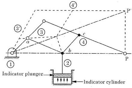
Fig. Engine Indicator
The point P at the end of link 4 (lever) records the variation of pressure in the cylinder and traces out approximately a straight line. As the mechanism uses link 4 and 2 (abc) as levers, it is also called as double lever mechanism.
Question.9. Explain crank and slotted lever quick return motion mechanism with the help of neat sketch.
Answer.
This mechanism is used in shapers, slotting machines etc. This mechanism is shown in fig.
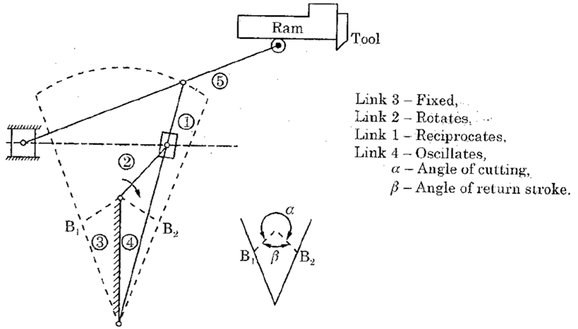 Fig. Crank and Slotted Lever Quick Return Motion Mechanism
In this mechanism, the slider 1 reciprocates in oscillating slotted lever 4 and link 2 rotates whole link 3 is fixed. Another link 5 connects the end of the link 4 to ram. The latter carries the cutting tool which reciprocates perpendicular to the fixed link 3.
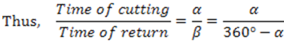
The ram and hence the cutting tool reverse its direction of motion when link 2 is perpendicular to link 4. The cutting stroke takes place during angle  whereas return stroke i.e. idle stroke is executed during crank rotation of angle
  which is equal to
  .
.
Question.10. Explain elliptical trammel with the help of neat sketch.
Answer. It is a device used for drawing ellipses. Fig. shows the elliptical trammel which has two grooves cut at right angles in a fixed plate. In the grooves, two sliding blocks are fitted. The link 2 joins the sliding blocks. At any point on the link 2 or on its extension traces out an ellipse on the fixed plate, when relative motion occurs.
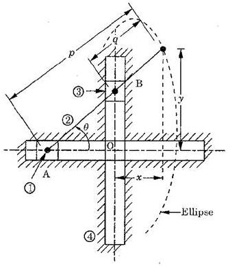
Fig. Elliptical Trammel
Question.11. Explain Oldham’s coupling with the neat sketch.
Answer.
It is meant for transmission of power from one shaft to another shaft to another shaft parallel to each other when the distance between the two axes is small and variable. The shafts are connected in a such a way that if one rotates, the other shaft rotates at the same speed and in the same direction. The shaft to be connected have flanges at their ends with slots cut in them. These form link 1 and 3 as shown in fig. An intermediate disc, circular in shape and having projections at right angles, suitable for slots in flanges gets fitted in the flanges and become link 4 which makes the sliding pair with link 1 and link 3.
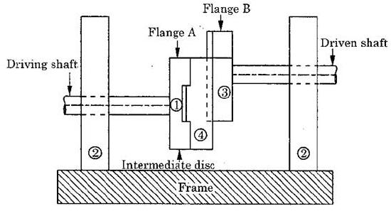
Fig. Oldham’s Coupling
When the driving shaft rotates, the flange A (link 1) rotates with it, which in turn rotates the intermediate disc (link 4) which further rotates flange B i.e., link 3. Thus, the motion is transmitted from one shaft to another shaft.