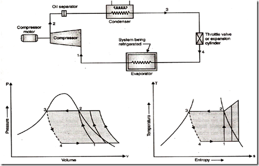
Vapour Compression Refrigeration Cycle:
The system constitutes a number of flow processes carried out in separate components namely compressor, condenser, expansion valve or capillary tube and evaporator. The working medium is always a liquid gas, i.e., CO2, NH3 and Freon etc. Liquid gas is a fluid which at normal temperature may exist either as a liquid or as a gas depending upon pressure. The refrigerant is not allowed to leave the system but is circulated again and again, alternately condensing and evaporating.
Fig. shows the schematic arrangement, P-V and T-5 diagram of a simple vapour-compression refrigeration cycle.
The sequence of operation of the cycle is:
1. Reversible adiabatic compression (1-2): The vapour at a low pressure P1 temperature Tl and preferably dry (state 1) is drawn from the evaporator during suction stroke of the compressor. During compression, the vapour is compressed isentropic ally to a higher pressure P2 and temperature T2. At compressor exit, the vapour may be wet, dry or superheated. In addition to raising the pressure of vapour, the compressor creates the pressure difference between the evaporator and condenser and that maintains a continuous flow of refrigerant through the system.
The compressor is of rotary type for domestic refrigerators and of reciprocating type for large plants and machines, viz., ice plants and cold storages. For plants with capacity over 50 tons, centrifugal compressors are used and these are directly coupled with high speed gas turbines or electrical controls.
2. Constant pressure condensation (2-3): The vapour refrigerant at high temperature and pressure (state 2) coming from the compressor is delivered to the condenser where its condensation takes place at constant pressure. The condenser first absorbs the heat of superheat and the temperature of the vapour falls to saturation temperature. Subsequently the refrigerant loses its latent heat and is changed into a high pressure liquid (state 3). For small machines (i.e. domestic refrigerators), the cooling medium is atmosphere and for larger units it may be a stream of water.
3. Throttling (3-4): The expansion of the high pressure liquid refrigerant is done by the throttling process. During throttling pressure drops but the enthalpy remains constant. Due to drop in pressure, the liquid starts boiling and the required heat is provided by the refrigerant itself. Consequently the temperature falls and at throttle exit, the refrigerant is a mixture of liquid and vapour (very wet vapour of 10 to 20% quality). Throttling is an irreversible process and has been shown by dotted line on T-S plot. The throttling device may be a capillary tube, a thermostatic expansion valve, an automatic expansion valve and float valve etc.
4. Constant pressure evaporation (4-1): The wet vapour after throttling passes through evaporator coils placed in the medium (usually brine) which is to be cooled. Since the temperature of the vapour is below that of brine, it absorbs latent heat from the brine and gets evaporated at constant pressure. The vaporization continues upto state point 1 and this stage of the refrigerant depends upon the heat absorbed. The refrigerant may remain wet, become dry saturated or get slightly superheated.
To complete the refrigerant cycle, the refrigerant vapour from the evaporator is routed back into the compressor.
The components of the refrigeration system are connected by pipes such as:
Suction line that conveys the low pressure vapour from the evaporator to the suction inlet of the compressor. Discharge line (or hot gas line) that delivers the high pressure, high temperature refrigerant from the compressor to the condenser.
Liquid line that carries the liquid refrigerant from the receiver tank to the expansion/ throttle valve. The receiver tank installed between the condenser and expansion device provides storage for the condensed liquid so that a constant supply of liquid is assured to the evaporator as per requirement.
