To study the constructional features of Lancashire Boiler
AIM: To study the constructional features of Lancashire Boiler
APPARATUS: LANCASHIRE BOILER
Lancashrie boiler is a horizontal internally fired, natural circulation fire tube boiler. This boiler rises steam upto a pressure of its bar and maximum evaporating capacity of 8500 Kg of steam per hour. This boiler is very widely used in sugar mills and chemicals products industries where the steam is required for processing work.
CONSTRUCTION:
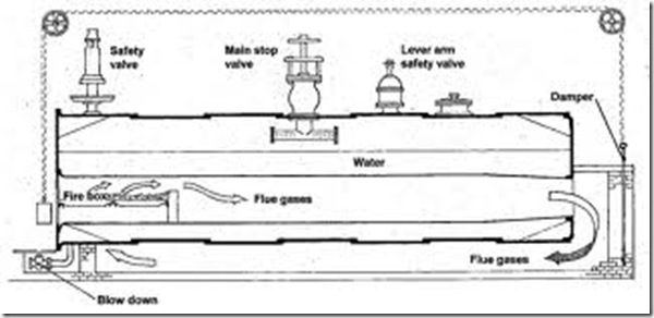
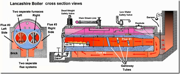
The boiler consist of a horizontal shell placed on a brick work tubes of diameter about 0.4 times of that of the boiler shell and runs through out its length. In each of these flue inside of their front end. The space underneath the grate is the ash pit.
The brick work setting is designed so as the provide an enclosed chamber for each of the flue tubes at the rear end of the boiler shell, which are connected to the bottom central channel which unturn is connected to the side channel 1 and 2 at their front end. The two side channel are connected at their rear end to a common rear passage which is connected to the chimney.
Figure of LANCASHIRE BOILER
The boiler shell is filled with water to three-fourth of its volume which will submerge both the flue tubes. The remaining space above the surface of the water in the boiler shell is the steam space.
PATH OF FLUE GASES:
When flue is charged on the furnace door sufficient amount of air also enters the area of the grate the hot gases produced by burning of the fuel initially in their first run pass along the length of the flue tube through them from the front end to the rear end of the boiler. As these hot gases pass through the flue tubes heat transfer takes place from the hot gases to the water through less emerges from both the flue tubes into the respective near enclosed chamber provided at the rear end of the boiler shell. Now on their second run from the rear enclosed chamber provided at they pass downwards and unite in the bottom central channel and travel from the rear end to the front end of the boiler. During this path of the hot gases the heat transfer takes place from the hot gases to the water through the bottom portion of the boiler shell. Exposed to the bottom central channel. After passing along divided at the front end of the boiler shell and enter into the side channel 1 and 2 and in their third run pass through them to the rear end of the boiler. The hot gases emerging at the rear end of the side channel 1 and 2 reunite in the rear passage and make their exit to the chimney through the rear passage. During the path of the hot gases in the side channel 1 and 2 the heat transfer takes place from the hot gases the water through the portion of the boiler shell exposed to the side channels. The steam accumulated in the steam space is taken out through the steam stop valve.
The boiler is mounted with essential mounting and accessories like steam stop valve, safety valve blow of valve pressure gauge, water gauge etc. at shown at their appropriate places. The super heater which consists of a set of U tubes is placed at the rear end of the shell. The flue gases before they are passed into the bottom central channel heats up the steam in the super heater tubes and convert into super heater steam.


One Response to “To study the constructional features of Lancashire Boiler | BME Lab Manual”
Anyewi George
its complicated