To study constructional features of Pelton Turbine.
OBJECT : To study constructional features of Pelton Turbine.
APPARATUS USED: Model of Pelton Turbine
THEORY:
PELTON TURBINE
A pelton turbine is a tangential flow impulse turbine. The water strikes the bucket along the tangent of the runner. The energy available at the inlet of the turbine is only kinetic energy.
Water from the reservoir is brought to the turbine through penstocks, at the end of which a nozzle is fitted. The nozzle converts whole of the available head into the kinetic head in the form of a high velocity jet. The jet strikes the buckets mounted on the rim of a wheel called runner. The force of jet causes the runner to rotate and mechanical power is produced. In the end, the water goes to the tail race.
Number of nozzles depend upon specific speed. However, maximum number of nozzles can be up to 6.
Components of a pelton turbine
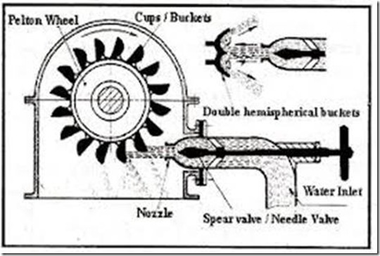
1. Runner with Bucket: The runner of a pelton turbine consists of a number of double cupped buckets surrounded to the periphery of the wheel. Each bucket has a sharp edge at the centre called the splitter. The water strikes each bucket at this splitter and is divided into two sides, thus avoiding any unbalanced thrust on the shaft. It is shown in fig.
To get full reaction of the jet, it should to be turned through 180O by the bucket. But then, the jet may strike the incoming bucket retarding the speed of the runner. Therefore, the angle through which the jet is turned is kept between 160O to 170O. Average value is taken as 165O.
The bottom portion of the bucket is usually cut which also facilitates the jet to pass through the succeeding bucket.
Figure of Pelton Turbine
Material for bucket is cast iron for low head plant and cast steel, stainless steel and bronze for medium and high heads. The buckets are either cast integral with the wheel or bolted to the rim.
Bolted arrangement is preferred as the damaged bucket can be easily replaced.
2. Nozzle with guide mechanism: The function of the nozzle of a pelton wheel is to convert the available pressure energy into high velocity energy in the form of jet. The quantity of water required is proportional to the load on the turbine. Therefore, to control the flow through the nozzle, some most of a regulating or a governing mechanism is necessary. This is generally done by using a spear inside the nozzle.
The movement of spear inside the nozzle changes the area of flow through it, thus varying the discharge. The movement of the spear is affected by a governor through a servomechanism. The governor itself is operated by the turbine shaft. If the load on turbine reduces and the runner tries to speed up, the governor will be activated, the action of governor is to move the spear into the nozzle to reduce the area of flow. This reduces the discharge through the nozzle. Reverse will happen if the load increases on turbine shaft.
A small brake nozzle is used in case of large turbine. When the wheel is to be stopped, besides cutting off the supply of water through the main nozzle. The brake nozzle also directs the water on to the back of buckets to bring the wheel quickly to rest.
3. Casing : Casing of a pelton turbine is not to perform any hydraulic function. However, a casing is necessary to avoid accidents, splashing race and to support the housing for the bearing and the nozzle.

3 Responses to “To study constructional features of Pelton Turbine | BME Lab Manuals”
dedicated hosting
Very quickly this web page will be famous among all blogging and site-building viewers, due to it’s pleasant articles or reviews|
Anil kumar yadav
Good things
admin
Thanks for the appreciation.