Solved problems based on CAM Profiles
Cam is a very important topic in the kinematics of machines or theory of machines. Here we are presenting some solved problems based on cam profiles. Although we checked the errors, but if you mark some error, let us known in the comment box.
(1) Draw the cam profile for following conditions:
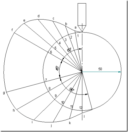
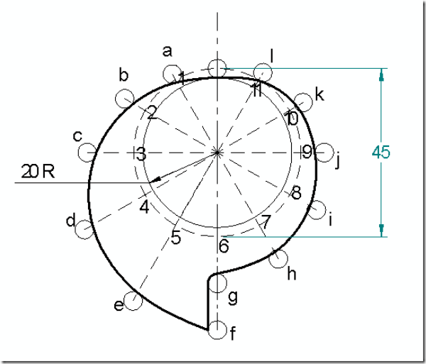
Follower type = Knife edged, in-line; lift = 50mm; base circle radius = 50mm; out stroke with SHM, for 600 cam rotation; dwell for 450 cam rotation; return stroke with SHM, for 900 cam rotation; dwell for the remaining period. Determine max. velocity and acceleration during out stroke and return stroke if the cam rotates at 1000 rpm in clockwise direction.
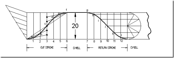
Displacement diagram:
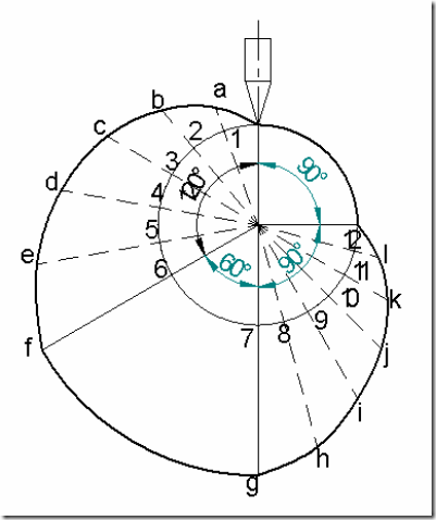
Cam profile: Construct base circle. Mark points 1,2,3…..in direction opposite to the direction of cam rotation. Transfer points a,b,c…..l from displacement diagram to the cam profile and join them by a smooth free hand curve. This forms the required cam profile.
Calculations:
Angular velocity of cam = ![]() =104.76 rad/sec
=104.76 rad/sec
Max. velocity of follower during outstroke = vomax = ![]() =
=
Similarly Max. velocity of follower during return stroke = , vrmax = ![]() =
=
Max. acceleration during outstroke = aomax = rω2p (from d3) = ![]() =
=
=  2469297.96mm/sec2 = 2469.3m/sec2
Similarly, Max. acceleration during return stroke = armax = ![]() =
=
=  1097465.76mm/sec2 = 1097.5m/sec2
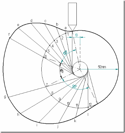
(2) Draw the cam profile for the same operating conditions of problem (1), with the follower off set by 10 mm to the left of cam center.
Displacement diagram: Same as previous case.
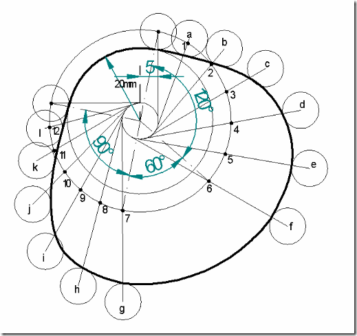
Cam profile: Construction is same as previous case, except that the lines drawn from 1,2,3…. are tangential to the offset circle of 10mm dia. as shown in the fig.
(3) Draw the cam profile for following conditions:
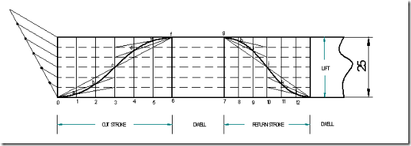
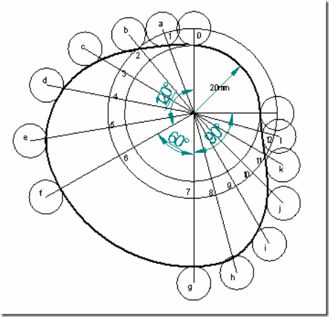
Follower type = roller follower, in-line; lift = 25mm; base circle radius = 20mm; roller radius = 5mm; out stroke with UARM, for 1200 cam rotation; dwell for 600 cam rotation; return stroke with UARM, for 900 cam rotation; dwell for the remaining period. Determine max. velocity and acceleration during out stroke and return stroke if the cam rotates at 1200 rpm in clockwise direction.
Displacement diagram:
Cam profile: Construct base circle and prime circle (25mm radius). Mark points 1,2,3…..in direction opposite to the direction of cam rotation, on prime circle. Transfer points a,b,c…..l from displacement diagram. At each of these points a,b,c… draw circles of 5mm radius, representing rollers. Starting from the first point of contact between roller and base circle, draw a smooth free hand curve, tangential to all successive roller positions. This forms the required cam profile.
Calculations:
Angular velocity of the cam = ![]() 125.71rad/sec
125.71rad/sec
Max. velocity during outstroke =![]() =
=
Max. velocity during return stroke = 
= 3999.86mm/sec = 3.999m/sec
Acceleration of the follower during outstroke =  =
=
=  359975mm/sec2 = 359.975m/sec2
Similarly acceleration of the follower during return stroke = ![]() =
=
=  639956mm/sec2 = 639.956m/sec2
(4) Draw the cam profile for conditions same as in (3), with follower off set to right of cam center by 5mm and cam rotating counter clockwise.
Displacement diagram: Same as previous case.
Cam profile: Construction is same as previous case, except that the lines drawn from 1,2,3…. are tangential to the offset circle of 10mm dia. as shown in the fig.
(5) Draw the cam profile for following conditions:
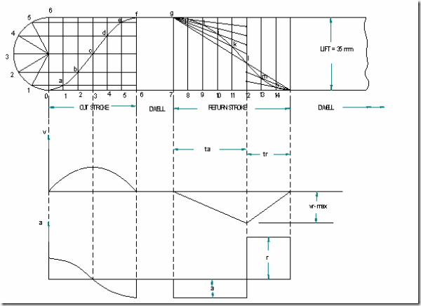
Follower type = roller follower, off set to the right of cam axis by 18mm; lift = 35mm; base circle radius = 50mm; roller radius = 14mm; out stroke with SHM in 0.05sec; dwell for 0.0125sec; return stroke with UARM, during 0.125sec; dwell for the remaining period. During return stroke, acceleration is 3/5 times retardation. Determine max. velocity and acceleration during out stroke and return stroke if the cam rotates at 240 rpm.
Calculations:
Cam speed = 240rpm. Therefore, time for one rotation = ![]()
Since acceleration is 3/5 times retardation during return stroke,
Displacement diagram is constructed by selecting ta and tr accordingly.
Angular velocity of cam = ![]() =25.14 rad/sec
=25.14 rad/sec
Max. velocity of follower during outstroke = vomax = ![]() =
=
Similarly Max. velocity during return stroke = ![]()
= 559.9 mm/sec = 0.56m/sec
Max. acceleration during outstroke = aomax = rω2p (from d3) = ![]() =
=
=  69127.14mm/sec2 = 69.13m/sec2
acceleration of the follower during return stroke =  = 7166.37 mm/sec2 = 7.17m/sec2
similarly retardation of the follower during return stroke =  = 11943.9 mm/sec2 = 11.94m/sec2
(6) Draw the cam profile for following conditions:
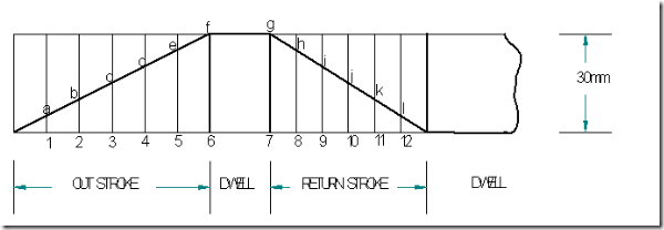
Follower type = knife edged follower, in line; lift = 30mm; base circle radius = 20mm; out stroke with uniform velocity in 1200 of cam rotation; dwell for 600; return stroke with uniform velocity, during 900 of cam rotation; dwell for the remaining period.
Displacement diagram:
Cam profile:
(7) Draw the cam profile for following conditions:
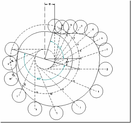
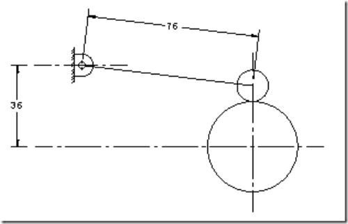
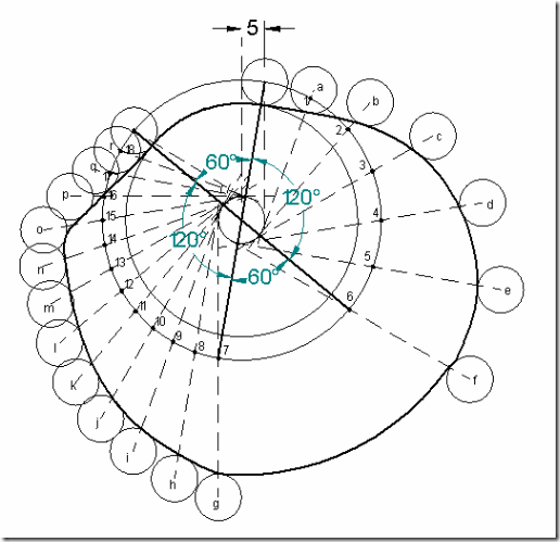
Follower type = oscillating follower with roller as shown in fig.; base circle radius = 20mm; roller radius = 7mm; follower to rise through 400 during 900 of cam rotation with cycloidal motion; dwell for 300; return stroke with cycloidal motion during 1200 of cam rotation; dwell for the remaining period. Also determine the max. velocity and acceleration during outstroke and return stroke, if the cam rotates at 600 rpm.
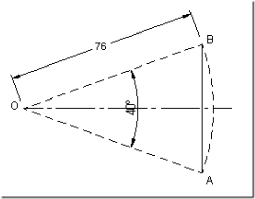
Lift of the follower = S = length AB ![]() arc AB =
arc AB = ![]() = 53 mm.
= 53 mm.
Radius of cycloid generating circle = ![]() = 8.4 mm
= 8.4 mm
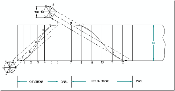
Displacement diagram;
Angular velocity of cam = ![]() = 62.86 rad/sec
= 62.86 rad/sec
vomax = Max. velocity of follower during outstroke =  = 4240.2 mm/sec
vrmax = Max. velocity of follower during return stroke =  = 3180 mm/sec
aomax = Max. acceleration during outstroke =
= 533.1 m/sec2.
armax = Max. acceleration during return stroke =
 = 299855.8mm/sec2 = 299.8 m/sec2.
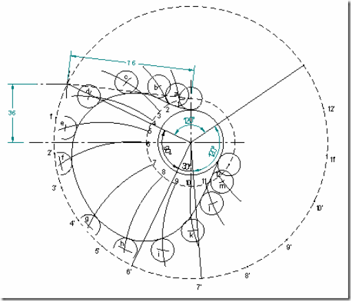
Cam profile: Draw base circle and prime circle. Draw another circle of radius equal to the distance between cam center and follower pivot point. Take the line joining cam center and pivot point as reference and draw lines indicating successive angular displacements of cam. Divide these into same number of divisions as in the displacement diagram. Show points 1’, 2’, 3’… on the outer circle. With these points as centers and radius equal to length of follower arm, draw arcs, cutting the prime circle at 1,2,3…. Transfer points a,b,c.. on to these arcs from displacement diagram. At each of these points a,b,c… draw circles of 7mm radius, representing rollers. Starting from the first point of contact between roller and base circle, draw a smooth free hand curve, tangential to all successive roller positions. This forms the required cam profile.
(8) Draw the cam profile for following conditions:
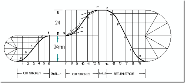
Follower type = knife edged follower, in line; follower rises by 24mm with SHM in 1/4 rotation, dwells for 1/8 rotation and then raises again by 24mm with UARM in 1/4 rotation and dwells for 1/16 rotation before returning with SHM. Base circle radius = 30mm.
Angle of out stroke (1) = θ01 = ![]()
Angle of out stroke (2) = θ02 = ![]()
Displacement diagram:
Cam profile:
(9) Draw the cam profile for following conditions:
Follower type = flat faced follower, in line; follower rises by 20mm with SHM in 1200 of cam rotation, dwells for 300 of cam rotation; returns with SHM in 1200 of cam rotation and dwells during the remaining period. Base circle radius = 25mm.
Displacement diagram:
Cam profile: Construct base circle. Mark points 1,2,3…..in direction opposite to the direction of cam rotation, on prime circle. Transfer points a,b,c…..l from displacement diagram. At each of these points a,b,c… draw perpendicular lines to the radials, representing flat faced followers. Starting from the first point of contact between follower and base circle, draw a smooth free hand curve, tangential to all successive follower positions. This forms the required cam profile.
(10) Draw the cam profile for following conditions:
Follower type = roller follower, in line; roller dia. = 5mm; follower rises by 25mm with SHM in 1800 of cam rotation, falls by half the distance instantaneously; returns with Uniform velocity in 1800 of cam rotation. Base circle radius = 20m.
Displacement diagram:
Cam profile:
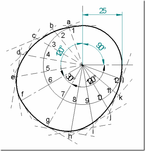
(11) Draw the cam profile for following conditions:
Follower type = roller follower, off-set to the right by 5mm; lift = 30mm; base circle radius = 25mm; roller radius = 5mm; out stroke with SHM, for 1200 cam rotation; dwell for 600 cam rotation; return stroke during 1200 cam rotation; first half of return stroke with Uniform velocity and second half with UARM; dwell for the remaining period.
Displacement diagram:
Cam profile:
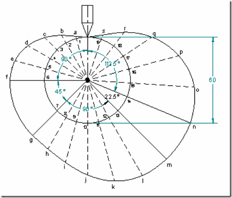
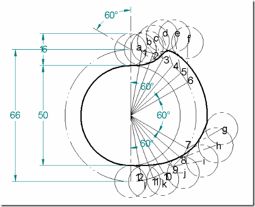
(12) A push rod of valve of an IC engine ascends with UARM, along a path inclined to the vertical at 600. The same descends with SHM. The base circle diameter of the cam is 50mm and the push rod has a roller of 60mm diameter, fitted to its end. The axis of the roller and the cam fall on the same vertical line. The stroke of the follower is 20mm. The angle of action for the outstroke and the return stroke is 600 each, interposed by a dwell period of 600. Draw the profile of the cam.
Displacement diagram:
Cam profile:










39 Responses to “Solved problems based on CAM Profiles | Kinematics of Machines Tutorials”
Adenaya Demilade
Wow!!!The solved examples has helped me a lot. Now I see how the whole thing really is…. thanks guys
admin
Thanks for the appreciation
priya
Grt…!! Was quite helpful
admin
Thanks, comment more if you need anything else.
ivan
guys i need help! a cam is required for an automated transfer mechanism. The cam follower must rise outward 1.0 inch with constant velocity in 3.0 seconds, dwell for 0.5 seconds, fall with constant velocity 2.0 seconds, and then repeat the sequence. Determine the required speed of the cam.
admin
Hello,
one rotation in 5.5 second
In one second, the cam rotates 1/5.5 times
In one minute, the cam rotates for 60/5.5 times
So the speed in rpm would be 10.90 rpm
However, if you rest the cam after the function that is second dwell for 0.5 seconds, You need 10 rpm.
Precisely, I think you need cam profile.
Enjoy!!
SHUBHAM
A cam with a minimum radius of 25 mm,
rotating in clockwise direction with a uniform
speed
of 100 rpm is to be designed to give the motion for
a roller follower as follows.
(i) To raise through 50
mm during 120° rotat
ion of cam with SHM. (ii)
Fully raised through
next 30°. (iii) To lower during
next 60° with UAUR. (iv) Dwell for the remaining
period.
Draw the profile of the cam when the line of
stroke of the follower is offset by 15 mm from
the
axis of the camshaft……..I need the solution of ths
admin
Thanks for the comment.
Will try to get a solution and mail u.
Ishan
Awesome examples!Thanks
admin
Thanks for the appreciation.
Anyewi George
good constructions
Daniel Amine
I found this very useful in preparing for my classes.
Best wishes
admin
Thanks. Please send feedback/suggestions for improvement.
Chinmay
Need to know the scheme of valuation of the cam .plz.
Nikhil
If speed is given is counter clockwise than how to draw profile of cam
SITHIVINAYAGAM N
sir its fantastic work, only one help sir may i get copy of work to my mailid. Pls
Madhu
Sir how can we divide the 6 equal part of outstroke and return stroke. If we have 60° outstroke and 90° return stroke then how can I divide both of them in 6 equal parts . please solve it and inform me .
Yusuf musa
I spend a lot of my time for preparing my Classes
juny
it is very helpful to my subject. sir can i ask a pdf copy for this in my email because our internet connection here is very limited?
admin
Thanks for liking it.
I will try to send an email to your mail.
Thanks again.
BALASUBRAMANIAN
Draw the profile of a cam to give the following motion to a roller follower; Output stroke during 50 of cam rotation, dwell for 10 of cam rotation, return stroke during 50 of cam rotation and dwell for the remaining 250 of cam rotation. The stroke of the follower is 2.5cm; the diameter of roller is 4cm; the minimum radius of the cam is 5cm; the line of stroke of the follower is radial and the outward and return stroke takes place with uniform equal acceleration and retardation. pls solve the problems
admin
Thanks for the comment. It is not possible for me to explain here. But I will try.
Nishigandha
I want to design a cylindrical cam and follower mechanism.Can you help me with the force calculations.??
admin
Sure, Will pass this on. Someone will definitely do.
K. Manimaran
Sir I need tangent cam and circular arm notes……… Plz help me sir
K. Manimaran
How to draw tangent cam profile diagram?
Tifany
This is very helpful information you provided. Thank you.Can we have it in the form of aPdf as well
Gaurav
The acceleration being 2/3 of retardation for 150° of cam roatation with UARM.
Sudarshan
Please give solution for this problem
Construct a disc cam to give uniform motion to a knife edge follower during stroke of 50 mm during the first half of the cam revolution, The follower gain returns to its original position with uniform motion during the next half the revolution. The minimum radius of the cam is 50 mm and the diameter e can shaft is 35 mm. Draw the profile of the cam when the axis of passes through the axis of cam shaft.
Angelina
Derive an expression for the velocity and acceleration of a flat end follower when it is at the base and nose of a straight flanked cam.Furthermore,if the follower is a knife edge type. What would be the expressions for its velocity and acceleration?
Raja
Sir,
How to calculate the diameter of the roller follower, if not given….
the problem is based on “design of cams and cam followers”….
kindly help me to get through this…
Madhuri
Please solve the problems on cams with specified counters
Anand Golasangi
Thanks sir very useful in your notes very esaly solve the problems
Vaishnavi Malwadkar
All types are covered!! Ty
Vaishnavi Malwadkar
When lift and oscillating angle with follower length given what should we consider while drawing given life or calculate new lift?
B. Vinod Kumar
A cam operating at uniform speed of 300RPM operates a reciprocating
follower through a roller 15 mm diameter. The follower motion is defined as below.
(I) Outward during 1500 with UARM
(ii) Dwell for next 300
(iii) Return during next 1200 with SHM
(iv) Remaining dwell period.
Stroke of the follower is 30mm, minimum radius of the cam is 30 mm. Draw the
cam profile when the follower axis is offset to the right by 10mm. Determine
maximum velocity and acceleration during the outstrok
Patootie
Helpp! A cam drives a flat reciprocating follower in the following manner. During the first 90° rotation of the cam, the follower moves outward through a distance of 30 mm with SHM. The follower dwells during next 90° cam rotation. During the next 90° cam rotation, the follower moves inward with SHM. The follower then dwells for next 90° cam rotation. Draw the cam profile and calculate the maximum values of velocity and acceleration when cam rotates at 10 rad/s.
Abemelek Melkamu Mekonenn
cam shaft=30mm base circle radius= 60mm lift of follower=65mm out stroke of cam=50deg dwell=45deg return stroke cam=90deg type of follower =Flat faced type of follower motion= translate location of action= Inline input shaft (rpm)=1500
Abemelek Melkamu Mekonenn
please answer me last time I asked you