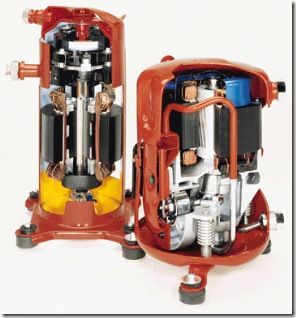
To study the cut sectional model of reciprocating, rotary and centrifugal compressor.
Apparatus used: – Cut sectional Model of Reciprocating, Centrifugal and Rotary compressor
Reciprocating compressor:
Theory: –
The compressors in which the vapour refrigerant is compressed by reciprocating motion of the piston are called reciprocating compressors. These compressors are used for refrigerant which have comparatively low volume per Kg and a large differential press. Such as NH3 (R-717), R-12, R-22 and CH3Cl (R-40). The reciprocating compressors are available in sizes as small as 1/2 KW which are used in small domestic refrigeration and up to about 150 KW for large capacity.
The two types of reciprocating compressor in general are: –
Single acting vertical compressor.
Double acting horizontal compressor.
The single acting compressors usually have their cylinder arranged vertically radially or in ‘V’ or ‘W’ form. The double acting compressors usually have their cylinder arranged horizontal.
Working: –
When the piston moves downwards, the refrigerant left in the clearance space expands. Thus, the volume of the cylinder increase and the pressure inside the cylinder decreases. When the pressure become slightly less than the valve gets opened and the vapour refrigerant flows into the cylinder. This flow continuous until the piston reaches the bottom of the stroke. At bottom of the stroke, the suction valve closes because of spring action. Now, when the piston moves upwards, the volume of the piston moves upwards, the volume of the cylinder decreases and the pressure inside the cylinder increases. When the pressure inside the cylinder becomes greater than that on the top of the discharge valve, the discharge valve gets opened & the vapour refrigerant is discharged into the condenser and the cycle is repeated.
The one on the left is a Scroll which is the newest type of compressor, and on the right is the old reliable Reciprocating compressor which has been used for years.
1. Work done during isothermal compression: –
Work done during suction stroke: – W1 = Area A B B’ A’ = p 1v1
Work done during Compression: – W2 = Area B C1 C1’ B’ = p1v1 loge (v1 / v2) Work done during Discharge: – = 2.3 m RT1 log r
2. Work done during polytropic compression: – (p v n = Constant)
Work done during suction stroke: – W1 = Area A B B’ A’ = p1v1
Work done during Compression: – W2 = Area BCC’ B’ = p2v2-p1v1/n – 1
Work done during Discharge: – W2 = Area CDA’C = p2v2
3. Work done during Isentropic Compression: – W = y / y-1 x m cp (y-1 / y) (T2-T1) = m cp (T1-T2) 9 Rotary compressor
Theory: – In rotary compressor, the vapour refrigerant from the evaporator is compressed due to movement of blades. The rotary compressors are positive displacement type compressor. Since, the clearance in rotary compressors is negligible; therefore, they have high i1vol. These may be used for refrigerants like R- 12, R-22, and R-144 & NH3.
The two types of rotary compressors are: – Single stationary blade type
Rotating blade type
Working: –
Single stationary blade type
It consists of a stationary cylinder, a roller and a shaft. The shaft has an eccentric on which the roller is mounted. A blade is set into the slot of a cylinder in such a manner that it always maintains contacts with a sloter by means of a spring. The blade moves in and out of the slot to follow the rotor when it rotates. Since the blade separates the suction and discharge parts, therefore it is often called a sealing blade. When the shaft rotates, the roller also rotates the roller rotates so that it always touches the cylinder wall.
Rotating Blade type
It consists of a cylinder and a slotted rotor containing a number of blades. The centre of the rotor is eccentric with the centre of the cylinder. The blades are forced against the cylinder wall by the centrifugal action during the rotation of the motor.
The low pressure and temperature vapour refrigerant from the evaporator is drawn through the suction port. As the rotor turns, the suction vapour refrigerant entrapped between the two adjacent blades is compressed. The compressed refrigerant at high pressure and temp is discharged through the discharge port to the condenser.
Centrifugal Compressor
The centrifugal compressor increases the pressure of low pressure vapour refrigerant to a high pressure by centrifugal force. The centrifugal compressor is generally used for refrigerants that require large displacement and low condensing pressure, such as R-12 is and R-113. However, the refrigerant R-12 is also employed for large capacity applications and low-temperature applications.
Theory:-
A single stage centrifugal compressor, in its simplest form, consists of an impeller to which a number of curved vanes are fitted symmetrically. The impeller rotates in an air volute casing with inlet and outlet points.
The impeller draws in low pressure vapour refrigerant from the evaporator. When the impeller rotates, it pushes the vapour refrigerant from the centre of the impeller to its periphery by centrifugal force. The high speed of the impeller leaves the vapour refrigerant at a high velocity at the vane tips of the impeller. The kinetic energy thus attained at the impeller outlet is converted into pressure energy when the high velocity vapour refrigerant passes over the diffuser. The diffuser is normally a vane less type as it permits more efficient part load operation which is quite and it further converts the kinetic energy into pressure energy before it leves the refrigerant to the evaporator.
Viva Questions
1. What is the effect of clearance volume in reciprocating compressor?
2. Draw ideal and actual P-V diagrams for a reciprocating compressor?
3. On what factors does the volumetric efficiency of a compressor depend?
4. What is the effect of compression index and the discharge pressure on volumetric efficiency?
5. What is a multi-stage compressor? Give its advantages.
6. What do you understand by hermetic sealed compressor? Give its advantages.
