To Determine COP and Tonnage capacity of a Air Conditioning system.
Apparatus: – Compressor, Condenser, Evaporator, Capillary Tube, Ammeter, Voltmeter.
Theory: –
Air conditioning equipment is used to maintain controlled atmospheric conditions as per required. The controlled atmospheric conditions may be required for human comfort or manufacturing processes of engineering goods. Air conditioning systems are classified in two groups.
1. Packed Units
2. Central Unit
A packed unit is self-contained unit, because complete unit including compressor, evaporator, condenser, fan motor etc. are kept in a common enclosure. Capacity of packed or window AC is 1 to 1.5 T.R. This AC is mounted with the room which is required for controlled atmosphere.
A window AC mainly consists of following sub-assemblies:
1 . System assembly includes compressor, condenser, evaporator, expansion device, and filter.
2. Motor with blower & fan assembly includes, a double ended shaft motor, a fan and a motor and suitable bracket for it.
3. Cabinet and air distributing assembly – it includes a cabinet as enclosure for whole system, an air distributing system.
4. Control panel assembly – it includes the switched those required to control the entire AC system as per the requirement, IC temperature, humidity etc.
The AC Test Rig is designed and fabricated, to determine the performance and to study its working principle. The AC test Rig consist a 1.5 T sealed compressor unit, a finned condenser (heating coil) and evaporator (cooling coil), a double ended (shaft) motor to run fan and blower simultaneously and fitted on a wooden stand and properly covered by grill. A duct is assembled along with blower unit as a carrier of comfort air, the velocity of the air passing through the coil is measured by using a pilot tube fitted in duct itself and connected to V-tube manometer which is fitted on control panel. The control panel is fitted over compressor and fan- blower assembly. Control panel consist of 1 phase energy meter to measure power consumed by compressor, a Rota meter to measure flow rate of refrigerant pressure gauge to measure pressure of discharge side compound vacuum gauge to measure suction side pressure, a digital temperature indicator to measure temperature at
various places. The desired temperature find out by changing position of selector switch with it. A voltmeter and ammeter is also fitted on control panel.
Specifications of AC Test Rig:
Compressor :
Hermetically sealed compressor 1.5 T.R. with starting and running capacitor.
Refrigerant :
R – 22
Pressure gauge :
0.300 PSI
Suction gauge :
– 30-0-150 PSI
Rota meter:
0 – 5 L L PM
Fan blower motor :
1 / 30 HP 1- 0
Condenser & evaporator :
Double row finned.
Window type air conditioner
The performance of an air-conditioning system is expressed in terms of co-efficient of performance. And COP is the ratio of net refrigerating effect and power supplied to do the work i.e.
COP = Rn / W
Where
Where
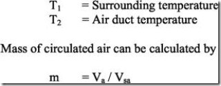
T1 – T2
Where
Procedure: –
Switch on the power supply to system i.e. start the compressor simultaneously start fan blower motor also. Now compressed refrigerant passing through the condenser and after condensing. It goes to evaporator, where due to cooling effect air, which is sucked by blower cools. After few minute the air at the outlet of air duct will become cool at that time. And also measure the static and total pressure by using V-tube manometer and pilot tube.
Temperature sensor details: –
1. T1 = Temperature Sensor : Fixed at Compressor Discharge Line
2. T2 = Temperature Sensor : Fixed after Condenser
3. T3 = Temperature Sensor : Fixed after Capillary Tube
4. T4 = Temperature Sensor : Inside Cooling Tank
5. T5 = Temperature Sensor : Fixed at Compressor Suction Line.
Observation Table
Sample Calculation
COP = m. CpΔT / KWh = 20 x 4.187 x (12) / 245 x 3.9
And C O P = m. CpΔT / W
Precautions: –
1. Run the system for quite some time before taking readings.
2. Note down number of revolutions of energy meter carefully with the help of stop watch.
3. Insure considerable cooled air output from air duct.
4. The system should not switch OFF immediately after once switched ON.
5. The control valve of pressure and compound gauge should open partly; when it is required to measure pressure otherwise valves must be closed.
6. Do not twist any pipe line and handle all switches valves very carefully only as and when required.
Result: –
Viva Questions: –
1. What do you mean by conditioning of air?
2. Explain the working principle of air conditioning system?
3. What are the different types of air conditioning system?
4. What are the various controls system used in air conditioning system?


