Cam nomenclature & Displacement Diagram for Different CAM Profiles
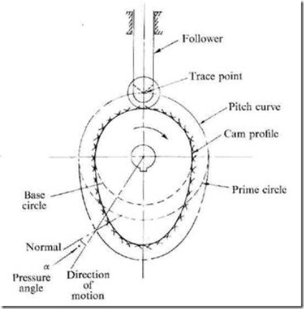
Fig. :Cam nomenclature
Cam Profile: The contour of the working surface of the cam.
Tracer Point: The point at the knife edge of a follower, or the center of a roller, or the center of a spherical face.
Pitch Curve: The path of the tracer point.
Base Circle: The smallest circle drawn, tangential to the cam profile, with its center on the axis of the camshaft. The size of the base circle determines the size of the cam.
Prime Circle: The smallest circle drawn, tangential to the pitch curve, with its center on the axis of the camshaft.
Pressure Angle: The angle between the normal to the pitch curve and the direction of motion of the follower at the point of contact.
Types of follower motion:
Cam follower systems are designed to achieve a desired oscillatory motion. Appropriate displacement patterns are to be selected for this purpose, before designing the cam surface. The cam is assumed to rotate at a constant speed and the follower raises, dwells, returns to its original position and dwells again through specified angles of rotation of the cam, during each revolution of the cam.
Some of the standard follower motions are as follows:
They are, follower motion with,
(a) Uniform velocity
(b) Modified uniform velocity
(c) Uniform acceleration and deceleration
(d) Simple harmonic motion
(e) Cycloidal motion
Displacement diagrams: In a cam follower system, the motion of the follower is very important. Its displacement can be plotted against the angular displacement θ of the cam and it is called as the displacement diagram. The displacement of the follower is plotted along the y-axis and angular displacement θ of the cam is plotted along x-axis. From the displacement diagram, velocity and acceleration of the follower can also be plotted for different angular displacements θ of the cam. The displacement, velocity and acceleration diagrams are plotted for one cycle of operation i.e., one rotation of the cam. Displacement diagrams are basic requirements for the construction of cam profiles. Construction of displacement diagrams and calculation of velocities and accelerations of followers with different types of motions are discussed in the following sections.
(a) Follower motion with Uniform velocity:
Fig.2 shows the displacement, velocity and acceleration patterns of a follower having uniform velocity type of motion. Since the follower moves with constant velocity, during rise and fall, the displacement varies linearly with θ. Also, since the velocity changes from zero to a finite value, within no time, theoretically, the acceleration becomes infinite at the beginning and end of rise and fall.
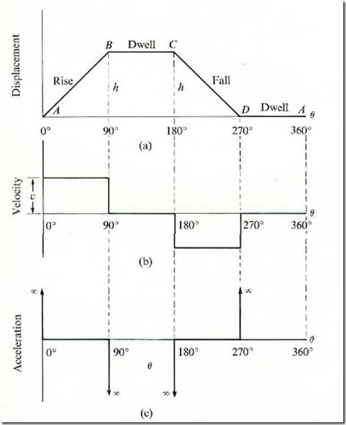 |
Fig.2: Follower motion with Uniform velocity
(b) Follower motion with modified uniform velocity:
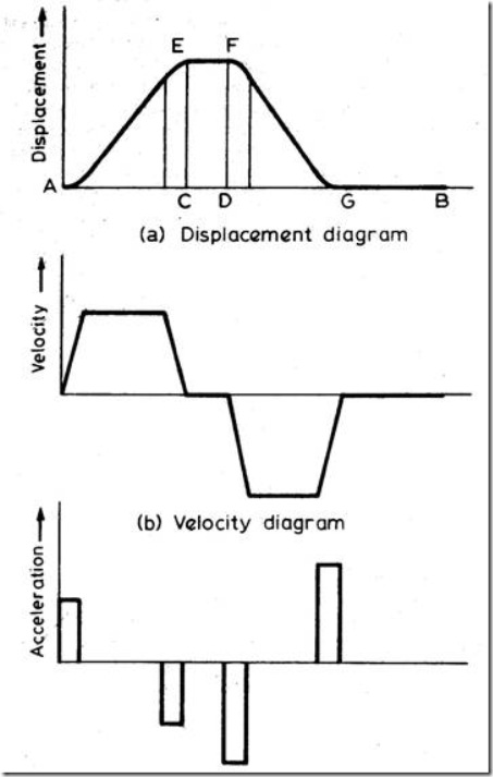
It is observed in the displacement diagrams of the follower with uniform velocity that the acceleration of the follower becomes infinite at the beginning and ending of rise and return strokes. In order to prevent this, the displacement diagrams are slightly modified. In the modified form, the velocity of the follower changes uniformly during the beginning and end of each stroke. Accordingly, the displacement of the follower varies parabolically during these periods. With this modification, the acceleration becomes constant during these periods, instead of being infinite as in the uniform velocity type of motion. The displacement, velocity and acceleration patterns are shown in fig. 3.
fig.3: Follower motion with modified uniform velocity
(c) Follower motion with uniform acceleration and retardation (UARM):
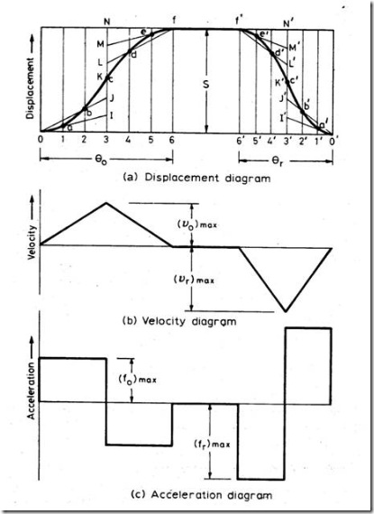
Here, the displacement of the follower varies parabolically with respect to angular displacement of cam. Accordingly, the velocity of the follower varies uniformly with respect to angular displacement of cam. The acceleration/retardation of the follower becomes constant accordingly. The displacement, velocity and acceleration patterns are shown in fig. 4.
Fig.4: Follower motion with uniform acceleration and retardation
s = Stroke of the follower
θo and θr = Angular displacement of the cam during outstroke and return stroke.
ω = Angular velocity of cam.
Time required for follower outstroke = to = ![]()
Time required for follower return stroke = tr = ![]()
Average velocity of follower = ![]()
Average velocity of follower during outstroke = 
vomin = 0
![]() = Max. velocity during outstroke.
= Max. velocity during outstroke.
Average velocity of follower during return stroke = 
vrmin = 0
![]() = Max. velocity during return stroke.
= Max. velocity during return stroke.
Acceleration of the follower during outstroke = 
Similarly acceleration of the follower during return stroke = ![]()
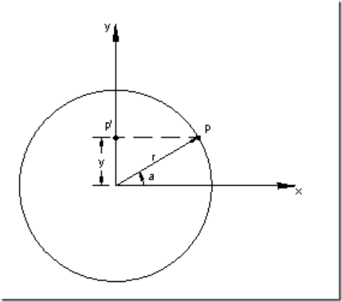
(d) Simple Harmonic Motion: In fig.5, the motion executed by point Pl, which is the projection of point P on the vertical diameter is called simple harmonic motion. Here, P moves with uniform angular velocity ωp, along a circle of radius r (r = s/2).
Fig.5: Simple Harmonic Motion
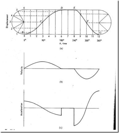
Fig.6: Follower Displacement Diagram with Simple Harmonic Motion
s= Stroke or displacement of the follower.
θo = Angular displacement during outstroke.
θr = Angular displacement during return stroke
ω = Angular velocity of cam.
to = Time taken for outstroke = ![]()
tr = Time taken for return stroke = ![]()
Max. velocity of follower during outstroke = vomax = rωp (from d2)
Similarly Max. velocity of follower during return stroke = , vrmax = ![]()
Max. acceleration during outstroke = aomax = rω2p (from d3) = 
Similarly, Max. acceleration during return stroke = armax = 
(e) Cycloidal motion:
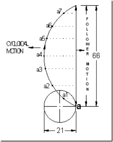
Cycloid is the path generated by a point on the circumference of a circle, as the circle rolls without slipping, on a straight/flat surface. The motion executed by the follower here, is similar to that of the projection of a point moving along a cyloidal curve on a vertical line as shown in figure 7.
Fig.7: Cycloidal motion
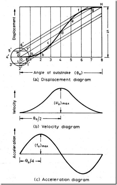
The construction of displacement diagram and the standard patterns of velocity and acceleration diagrams are shown in fig.8. Compared to all other follower motions, cycloidal motion results in smooth operation of the follower.
The expressions for maximum values of velocity and acceleration of the follower are shown below.
s = Stroke or displacement of the follower.
d = dia. of cycloid generating circle = ![]()
θo = Angular displacement during outstroke.
θr = Angular displacement during return stroke
ω = Angular velocity of cam.
to = Time taken for outstroke = ![]()
tr = Time taken for return stroke = ![]()
vomax = Max. velocity of follower during outstroke = ![]()
vrmax = Max. velocity of follower during return stroke = ![]()
aomax = Max. acceleration during outstroke = ![]()
armax = Max. acceleration during return stroke = ![]()
Fig. 8: Follower Displacement, Velocity & Acceleration Diagram for Cyloidal Motion
13 Responses to “Cam nomenclature & Displacement Diagram for Different CAM Profiles”
N.Ramaswamy
Very simple and clear presentation. Easily understandable by the students. Could you kindly work out a few problems based on these profiles?
admin
Thanks for the Comment. Send me the problems you need to solved.
Kalpesh Deshmukh
SIR PLEASE GIVE ME THE SOLUTION OF THIS PROBLEM Q.) A FLAT FACED RECIPROCATING FOLLOWER HAS THE FOLLOWING MOTIONS: 1) THE FOLLOWER MOVES OUT OF 80 DEGREE OF CAM ROTATION WITH UNIFORM ACCELERATION AND RETARDATION, THE ACCELERATION BEING TWICE THE RETARDATION. 2) THE FOLLOWER DWELLS FOR THE NEXT 80 DEGREE OF CAM ROTATION. 3) IT MOVES IN NEXT 120 DEGREE OF CAM ROTATION WITH UNIFORM ACCELERATION AND RETARDATION, THE RETARDATION BEING TWICE THE ACCELERATION. 4) THE FOLLOWER DWELLS FOR THE REMAINING PERIOD. THE BASE CIRCLE DIAMETER OF CAM IS 60 MM AND THE STROKE OF THE FOLLOWER IS 20 MM. THE LINE OF MOVEMENT OF THE FOLLOWER PASSES THROUGH THE CAM CENTRE. DRAW THE DISPLACEMENT DIAGRAM AND THE PROFILE OF THE CAM VERY NEATLY SHOWING ALL CONSTRUCTIONAL DETAILS.
Kalpesh Deshmukh
please give reply
admin
You would be able to find same type of problem in Theory of Machines by SS Rattan.
FRED
CAN YOU SEND ME THE PROCEDURAL
WAY OF CONSTRUCTING THESE CAMS
mohan
Pls giv solution for it. Got exam on 26-04-2016.
Design a cam with the base circle diameter of 40mm and width of 18mm.The valve moves with uniform acceleration and deacceleration for each half of the lift. Draw the cam profile with the above dimensions using design software.
B.S.Shankara
What is a bipolar cam? Please describe with a sketch and application
Akash
If the scale used for displacement diagram is different than that of constructing cam,does it wrong?
Deva prasad
Sir I need a solution for this question How to draw the answer i.e) Draw the crank angle vs. acceleration of the follower which is moving with uniform accelaration and retardation.
himasagar
A circular cam of diameter 100mm has an eccentric axis of rotation which is
offset 30mm from the centre. When used with a knife follower with its line of
action passing through the centre of rotation, what will be the difference
between the maximum and minimum displacements of the follower……………………need answer sir
himasagar
need solution…..A circular cam of diameter 100mm has an eccentric axis of rotation which is offset 30mm from the centre. When used with a knife follower with its line of action passing through the centre of rotation, what will be the difference between the maximum and minimum displacements of the follower
Yashwanth AR
I want information about cam